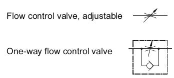
The symbol incorporates a non-return or check valve. But opting out of some of these cookies may affect your browsing experience. 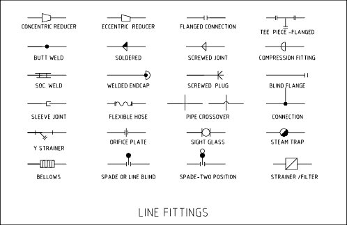 Both types can be either single-acting or double-acting. In an effort to improve both the speed and accuracyof creative design, we offer for your considerationand use this simplified system of symbols fordesigning pneumatic control circuitry. Pneumatic rotary cylinders are available in two main types: vane or swivel, and rack and pinion. The symbol for a compressor is similar to the air motor symbol. There also exist valves which are the opposite of this, called NOT-AND, or NAND valves. This makes it much easier for manufacturers and operators of machinery to identify individual parts and recognise their function. !A~FgnD?.x
  The spring pushes from the side it is drawn on and places the right side block diagram of the valve in function. These methods are increasingly common, but valves can still be actuated manually or mechanically, by means of push buttons, levers, rollers, toggles, etc. Cylinders using flexible cable or belts must be kept in tension.
Valve symbols includingsolenoid valve symbols are those that are in common use. For the purposes of identifying symbols, each of these components will be described individually.
12 The purpose of reducing or increasing the airflow or pressure in a pneumatic circuit, to slow down or accelerate the pneumatic system, a common application is for speed control of a pneumatic cylinder. 5/2 Bistable Manual Valve, Reversible, Detenting, 5/2 Monostable Manual Valve, Spring Return, 5/2 Monostable Pneumatic Valve, Spring Return, 5/2 Monostable Solenoid Valve, Spring Return. Pneumatic symbols were principally created to identify components on circuit design diagrams, but they can also be used on the components themselves. The International Organisation for Standardisation (ISO) is an independent, non-governmental body. 0000002008 00000 n 6 5-port 2-way valves have one Main Air, two Output Connections and two Exhaust ports and are commonly used for Double-Acting Cylinders. Thesesymbols are recommended for anyone with abasic understanding of pneumatic controlcomponents functions, and who seeks to designin a useful and productive manner. Symbols are used as a system of shorthand iconography thats shared within an industry or functional system across the world like traffic lights. 0000032394 00000 n pneumatic symbols valve common control simple instrumentation engineering learning automationdirect credit Single Acting Cylinder, Rear Spring with Position Sensing, Single Acting Cylinder, Front Spring with Position Sensing, Single Acting Cylinder, Front Spring, Through-rod with Position Sensing. Double Acting Cylinder, Fixed Mechanical Cushioning, Double Acting Cylinder, Fixed Mechanical Cushioning with Position Sensing, Double Acting Cylinder, Adjustable Cushioning, Double Acting Cylinder, Adjustable Cushioning with Position Sensing, Double Acting Cylinder, Self-adjusting Cushioning with Position Sensing, Double Acting, Through-rod, Fixed Mechanical Cushioning, Double Acting, Through-rod, Fixed Mechanical Cushioning, Hollow Piston Rod, Double Acting, Through-rod, Fixed Mechanical Cushioning with Position Sensing, Double Acting, Through-rod, Adjustable Cushioning with Position Sensing. These six basic valve symbols,when combined with the basic actuator symbols, comprise virtually allthe directional valve symbols needed for air logic control. This set of symbols pertains to various components of a pneumatically driven vacuum system. ), ( symbols pneumatic control directional valves common instrumentation engineering learning automationdirect credit 0000000836 00000 n On the 5-port valves used for Double-Acting Cylinders, the Port 3 Exhaust outlet is supplemented by a second Exhaust outlet at Port 5. 0000003275 00000 n h@[ydg` t,E*AAd:j$f}D=^q~#8Q8uepc)fy>7u9)(s)VoKUa/mh{GSw5uo|b?1n|i>]}oy%~nR.~.m/RVMJt_~V6\)\$ZT mvb]z[o;vV5gu8EFlE;NEAtElCW!C-,ZYh1dbE!;I,]#,,YtYdeE%.K],&qt8HtdE#FG,=Y4zh#L,r=Yzd7Eo @adXN,YHd=E{$HqdDXBdqHdqDHdqDHdqDHd1M_G7MnX^UO |H_ 0000002760 00000 n valve flow control pneumatic symbols valves direction return The letters EA indicate this is the exhaust port for the A circuit. We also use third-party cookies that help us analyze and understand how you use this website. pneumatic valve control gate symbol symbols instrumentation questions instrumentationtools answers One or more solid lines leading into/out of the tank indicate its intake/output lines. They can produce greater forces, and are used more commonly than single-acting cylinders.
So a valve with two ports in each of two boxes is a 2-port, 2-stage valve (2/2 Valve). Single Acting Cylinder, Front Spring, Through-rod, Hollow Piston Rod with Position Sensing. pneumatic symbols camozzi tech While a typical pneumatic system works by pushing objects away from the air source, pneumatic vacuum systems work by pulling objects towards it.
While it is still possible to carry out filtration, regulation and lubrication separately, its more common, and more efficient, to use a combined FRL unit. Directional valves comprise the largest portion of any air logic circuit.
They shouldbe both pictorial and functional in nature to helpthe designer visualize the circuit, and to providethe necessary pertinent information about howcomponents work (inputs, output, actuators, etc.). endstream endobj 204 0 obj <>stream 3/2 Bistable Normally Closed, Pneumatic, Spring Return, 3/2 Bistable Normally Closed, Solenoid, Spring Return, 3/2 Bistable Normally Closed, Solenoid, Monostable. 0000003466 00000 n On: 16-05-2019 Read Time: 23 minutes - Guides - Pneumatics. xb```U) cc`aX1E K =_W! Lockable isolation valves have an isolation lock that will block the input airflow to the valve for greater safety when servicing pneumatic equipment. nZn+z 8q,v=jGu D7&zIvB4)vY[!6u#E]&szBz`bx^)*[]iX)ym ^+5nJ X,#Hb. The components needed to manufacture andconstruct pneumatic logic control circuits arereadily available, reliable and have been proven incountless applications. 0000007845 00000 n Pilot and Solenoid Valves are switched indirectly from an external source, either another valve or an electric signal from a controller. pneumatic valve symbols mechanical ), ( These represent the operating states and describe the way the valve functions. The levels of detail for process equipment relates to the schematic type produced. Ports are the valve openings where pipes or hoses can be connected. Main air is what is supplied by the compressor and is shown by a circle with a dot at the centre and a connecting line from the circle. In a diagram, the manifold is shown as a cross junction within a square, offering more than one connection. xref pneumatic symbols valve control explained pneumatics operator In the bottom box, those two ports are both depicted as open (Normally Open, or NO), so that air may flow through the valve. Soft start valves emulate a 3/2 manual valve function, which limits the amount of air input directly to the valve, allowing pressure to build up gradually and venting excess air from the exhaust port. Magnets are often already attached to the piston internally by the manufacturer, so proximity sensors can detect the extension and retraction of the piston. Symbols created by combining valves and actuator. If there are only two boxes in the symbol this indicates a valve with only two positions, called a 2-stage valve. Connected lines are depicted with a solid dot at line junctions, such as T-junctions, while crossed over lines can either have no dot, or a directional arrow at the cross-over point. pneumatic manual valve symbols This means that it can have two positions or operating states for each 2-port valve (Input and Output: Open or Closed). pneumatic air compressed systems pneumatics engineering gcse weebly production Most valve symbols show the number of ports, number of positions and type of actuation. They must be fast and easy to draw. pneumatic symbols vacuum explained valve pneumatics control port ie Powered by, (
0000003694 00000 n Rowse, Units 5/6 Drake Mill Business Park, Estover Road, Plymouth, Devon, PL6 7PS, Copyright 2022. The more complex symbols involve considerable time in drawing them.
Once the compressed air has been filtered and regulated, it will have had oil and moisture removed. We Provide Tools and Basic Information for Learning Process Instrumentation and Control Engineering. valve is the sameregardless of how it is, https://www.clippard.com/cms/wiki/simplified-pneumatic-symbols. 0000002809 00000 n 7 electric, pneumatic, manual, etc. No heat is applied to objects in a pneumatic vacuum system, and they also suffer fewer issues with leakage. symbols pneumatic Valve gates such as OR, NOR, AND and NAND are almost identical in their function to similar electronic circuits, although they are somewhat different in form. A pilot actuator can operate a switch, or send signals to an actuator which will set its working pressure. 0000018012 00000 n 156 0 obj <> endobj Pneumatic Systems are still popular in older plants and even in modern plants where their use is inevitable. ), ( The symbols needed to design a pneumatic circuitare few, yet until now no practical rapid symbologyfor the control designer existed. Z&"E#p8kfhw_l>qr]*n?G0}of/1Gob=~l-%[z-oO;=nv{{fqEvllSnU+~kSj(wNx=I,{-$zqU"d/w87n6}f+##Ll7[ems{. These are cylinders that impart force by means of a mechanical slide or magnetic coupling, which is typically attached to a table or other component that travels along the cylinder body.
Actuators are understood to push the flow pathindicator when actuated, pushed or energized. hO0|G66CQ]?}\[zT&:? We'll assume you're ok with this, if you stay. 1 actuator drain
used in pneumatic logic control circuitry. What follows is a basic set of symbols designed tomeet these criteria. Similarly, 'air logic' or pneumatic logic is used to control the flow of air in a pneumatic system, by means of air logic valves. both Input 1 AND Input 1(3) must be present for Output 2 to function. 0000001760 00000 n The diamond shape is commonly used for all air conditioning components. The inverted triangle symbol Denotes an exhaust port. 0 :T&d80pL%bMC^ri{"LM;,`c5{ xuICs#"AK[86|yasF.o.NFV+q)>r5 > |S3Ve`b You also have the option to opt-out of these cookies. A coalescing filter works by using fibres in the filter element to attract minute moisture and oil particles. A cable cylinder still has an opening at one end, or both ends, but the piston rod is replaced by a flexible cable. A close study of most air logic control circuits will reveal that there areonly six basic valve functions commonly used. This category only includes cookies that ensures basic functionalities and security features of the website. Simplified symbols for faster, easier and This can slow us down in actually identifying the process in question and the relevant components. This symbol can also be shown with a zig-zag line to denote a spring-loaded check valve. When actuated, their linear movement causes the pinion gear and output drive shaft to rotate.
), Learning Instrumentation And Control Engineering, Industrial Motor Starters and Starting Methods, Electrical Protection of 3 phase Motors: Types and Protection Schemes, Understanding the Technical Specifications on the Nameplate of Solar Panels, A Guide to Solar Panels Power Installations, How to Specify Electric Motors for Hazardous Locations, Understanding Battery Technical Specifications, Instrumentation Books for Instrument Engineers and Technicians, Sizing Orifice Plates with Daniel Flow Calculator, Symbols of Directional Control Valves (Photo Credit: AutomationDirect.com), Pneumatic Valve Symbols (Photo Credit: AutomationDirect.com), Line Symbols in Pneumatic Symbols (Photo Credit: AutomationDirect.com), Symbols of Common Pneumatic Equipment.
Both types can be either single-acting or double-acting. In an effort to improve both the speed and accuracyof creative design, we offer for your considerationand use this simplified system of symbols fordesigning pneumatic control circuitry. Pneumatic rotary cylinders are available in two main types: vane or swivel, and rack and pinion. The symbol for a compressor is similar to the air motor symbol. There also exist valves which are the opposite of this, called NOT-AND, or NAND valves. This makes it much easier for manufacturers and operators of machinery to identify individual parts and recognise their function. !A~FgnD?.x The spring pushes from the side it is drawn on and places the right side block diagram of the valve in function. These methods are increasingly common, but valves can still be actuated manually or mechanically, by means of push buttons, levers, rollers, toggles, etc. Cylinders using flexible cable or belts must be kept in tension. Valve symbols includingsolenoid valve symbols are those that are in common use. For the purposes of identifying symbols, each of these components will be described individually.
12 The purpose of reducing or increasing the airflow or pressure in a pneumatic circuit, to slow down or accelerate the pneumatic system, a common application is for speed control of a pneumatic cylinder. 5/2 Bistable Manual Valve, Reversible, Detenting, 5/2 Monostable Manual Valve, Spring Return, 5/2 Monostable Pneumatic Valve, Spring Return, 5/2 Monostable Solenoid Valve, Spring Return. Pneumatic symbols were principally created to identify components on circuit design diagrams, but they can also be used on the components themselves. The International Organisation for Standardisation (ISO) is an independent, non-governmental body. 0000002008 00000 n 6 5-port 2-way valves have one Main Air, two Output Connections and two Exhaust ports and are commonly used for Double-Acting Cylinders. Thesesymbols are recommended for anyone with abasic understanding of pneumatic controlcomponents functions, and who seeks to designin a useful and productive manner. Symbols are used as a system of shorthand iconography thats shared within an industry or functional system across the world like traffic lights. 0000032394 00000 n pneumatic symbols valve common control simple instrumentation engineering learning automationdirect credit Single Acting Cylinder, Rear Spring with Position Sensing, Single Acting Cylinder, Front Spring with Position Sensing, Single Acting Cylinder, Front Spring, Through-rod with Position Sensing. Double Acting Cylinder, Fixed Mechanical Cushioning, Double Acting Cylinder, Fixed Mechanical Cushioning with Position Sensing, Double Acting Cylinder, Adjustable Cushioning, Double Acting Cylinder, Adjustable Cushioning with Position Sensing, Double Acting Cylinder, Self-adjusting Cushioning with Position Sensing, Double Acting, Through-rod, Fixed Mechanical Cushioning, Double Acting, Through-rod, Fixed Mechanical Cushioning, Hollow Piston Rod, Double Acting, Through-rod, Fixed Mechanical Cushioning with Position Sensing, Double Acting, Through-rod, Adjustable Cushioning with Position Sensing. These six basic valve symbols,when combined with the basic actuator symbols, comprise virtually allthe directional valve symbols needed for air logic control. This set of symbols pertains to various components of a pneumatically driven vacuum system. ), ( symbols pneumatic control directional valves common instrumentation engineering learning automationdirect credit 0000000836 00000 n On the 5-port valves used for Double-Acting Cylinders, the Port 3 Exhaust outlet is supplemented by a second Exhaust outlet at Port 5. 0000003275 00000 n h@[ydg` t,E*AAd:j$f}D=^q~#8Q8uepc)fy>7u9)(s)VoKUa/mh{GSw5uo|b?1n|i>]}oy%~nR.~.m/RVMJt_~V6\)\$ZT mvb]z[o;vV5gu8EFlE;NEAtElCW!C-,ZYh1dbE!;I,]#,,YtYdeE%.K],&qt8HtdE#FG,=Y4zh#L,r=Yzd7Eo @adXN,YHd=E{$HqdDXBdqHdqDHdqDHdqDHd1M_G7MnX^UO |H_ 0000002760 00000 n valve flow control pneumatic symbols valves direction return The letters EA indicate this is the exhaust port for the A circuit. We also use third-party cookies that help us analyze and understand how you use this website. pneumatic valve control gate symbol symbols instrumentation questions instrumentationtools answers One or more solid lines leading into/out of the tank indicate its intake/output lines. They can produce greater forces, and are used more commonly than single-acting cylinders.
So a valve with two ports in each of two boxes is a 2-port, 2-stage valve (2/2 Valve). Single Acting Cylinder, Front Spring, Through-rod, Hollow Piston Rod with Position Sensing. pneumatic symbols camozzi tech While a typical pneumatic system works by pushing objects away from the air source, pneumatic vacuum systems work by pulling objects towards it.
While it is still possible to carry out filtration, regulation and lubrication separately, its more common, and more efficient, to use a combined FRL unit. Directional valves comprise the largest portion of any air logic circuit.
They shouldbe both pictorial and functional in nature to helpthe designer visualize the circuit, and to providethe necessary pertinent information about howcomponents work (inputs, output, actuators, etc.). endstream endobj 204 0 obj <>stream 3/2 Bistable Normally Closed, Pneumatic, Spring Return, 3/2 Bistable Normally Closed, Solenoid, Spring Return, 3/2 Bistable Normally Closed, Solenoid, Monostable. 0000003466 00000 n On: 16-05-2019 Read Time: 23 minutes - Guides - Pneumatics. xb```U) cc`aX1E K =_W! Lockable isolation valves have an isolation lock that will block the input airflow to the valve for greater safety when servicing pneumatic equipment. nZn+z 8q,v=jGu D7&zIvB4)vY[!6u#E]&szBz`bx^)*[]iX)ym ^+5nJ X,#Hb. The components needed to manufacture andconstruct pneumatic logic control circuits arereadily available, reliable and have been proven incountless applications. 0000007845 00000 n Pilot and Solenoid Valves are switched indirectly from an external source, either another valve or an electric signal from a controller. pneumatic valve symbols mechanical ), ( These represent the operating states and describe the way the valve functions. The levels of detail for process equipment relates to the schematic type produced. Ports are the valve openings where pipes or hoses can be connected. Main air is what is supplied by the compressor and is shown by a circle with a dot at the centre and a connecting line from the circle. In a diagram, the manifold is shown as a cross junction within a square, offering more than one connection. xref pneumatic symbols valve control explained pneumatics operator In the bottom box, those two ports are both depicted as open (Normally Open, or NO), so that air may flow through the valve. Soft start valves emulate a 3/2 manual valve function, which limits the amount of air input directly to the valve, allowing pressure to build up gradually and venting excess air from the exhaust port. Magnets are often already attached to the piston internally by the manufacturer, so proximity sensors can detect the extension and retraction of the piston. Symbols created by combining valves and actuator. If there are only two boxes in the symbol this indicates a valve with only two positions, called a 2-stage valve. Connected lines are depicted with a solid dot at line junctions, such as T-junctions, while crossed over lines can either have no dot, or a directional arrow at the cross-over point. pneumatic manual valve symbols This means that it can have two positions or operating states for each 2-port valve (Input and Output: Open or Closed). pneumatic air compressed systems pneumatics engineering gcse weebly production Most valve symbols show the number of ports, number of positions and type of actuation. They must be fast and easy to draw. pneumatic symbols vacuum explained valve pneumatics control port ie Powered by, (
0000003694 00000 n Rowse, Units 5/6 Drake Mill Business Park, Estover Road, Plymouth, Devon, PL6 7PS, Copyright 2022. The more complex symbols involve considerable time in drawing them.
Once the compressed air has been filtered and regulated, it will have had oil and moisture removed. We Provide Tools and Basic Information for Learning Process Instrumentation and Control Engineering. valve is the sameregardless of how it is, https://www.clippard.com/cms/wiki/simplified-pneumatic-symbols. 0000002809 00000 n 7 electric, pneumatic, manual, etc. No heat is applied to objects in a pneumatic vacuum system, and they also suffer fewer issues with leakage. symbols pneumatic Valve gates such as OR, NOR, AND and NAND are almost identical in their function to similar electronic circuits, although they are somewhat different in form. A pilot actuator can operate a switch, or send signals to an actuator which will set its working pressure. 0000018012 00000 n 156 0 obj <> endobj Pneumatic Systems are still popular in older plants and even in modern plants where their use is inevitable. ), ( The symbols needed to design a pneumatic circuitare few, yet until now no practical rapid symbologyfor the control designer existed. Z&"E#p8kfhw_l>qr]*n?G0}of/1Gob=~l-%[z-oO;=nv{{fqEvllSnU+~kSj(wNx=I,{-$zqU"d/w87n6}f+##Ll7[ems{. These are cylinders that impart force by means of a mechanical slide or magnetic coupling, which is typically attached to a table or other component that travels along the cylinder body.
Actuators are understood to push the flow pathindicator when actuated, pushed or energized. hO0|G66CQ]?}\[zT&:? We'll assume you're ok with this, if you stay. 1 actuator drain
used in pneumatic logic control circuitry. What follows is a basic set of symbols designed tomeet these criteria. Similarly, 'air logic' or pneumatic logic is used to control the flow of air in a pneumatic system, by means of air logic valves. both Input 1 AND Input 1(3) must be present for Output 2 to function. 0000001760 00000 n The diamond shape is commonly used for all air conditioning components. The inverted triangle symbol Denotes an exhaust port. 0 :T&d80pL%bMC^ri{"LM;,`c5{ xuICs#"AK[86|yasF.o.NFV+q)>r5 > |S3Ve`b You also have the option to opt-out of these cookies. A coalescing filter works by using fibres in the filter element to attract minute moisture and oil particles. A cable cylinder still has an opening at one end, or both ends, but the piston rod is replaced by a flexible cable. A close study of most air logic control circuits will reveal that there areonly six basic valve functions commonly used. This category only includes cookies that ensures basic functionalities and security features of the website. Simplified symbols for faster, easier and This can slow us down in actually identifying the process in question and the relevant components. This symbol can also be shown with a zig-zag line to denote a spring-loaded check valve. When actuated, their linear movement causes the pinion gear and output drive shaft to rotate.
), Learning Instrumentation And Control Engineering, Industrial Motor Starters and Starting Methods, Electrical Protection of 3 phase Motors: Types and Protection Schemes, Understanding the Technical Specifications on the Nameplate of Solar Panels, A Guide to Solar Panels Power Installations, How to Specify Electric Motors for Hazardous Locations, Understanding Battery Technical Specifications, Instrumentation Books for Instrument Engineers and Technicians, Sizing Orifice Plates with Daniel Flow Calculator, Symbols of Directional Control Valves (Photo Credit: AutomationDirect.com), Pneumatic Valve Symbols (Photo Credit: AutomationDirect.com), Line Symbols in Pneumatic Symbols (Photo Credit: AutomationDirect.com), Symbols of Common Pneumatic Equipment.