Copy the code from below and upload it to the Arduino Nano Board. Open a new sketch File by clicking New. stepper code arduino motors drive transistor  This program drives a unipolar or bipolar stepper motor. * This example code is in the public domain, * Tutorial page: https://arduinogetstarted.com/tutorials/arduino-stepper-motor-and-limit-switch, // maximum of position we can set (long type). Note: The pins number are disordered as 8,10,9,11 on purpose. In detail, we are going to learn: If you do not know about stepper motor and limit switch (pinout, how it works, how to program ), learn about them in the following tutorials: This tutorial provides the Arduino codes for two cases: One stepper motor + one limit switch, One stepper motor + two limit switches. Please take a close look at this Arduino - Stepper Motor tutorial to see how to connect the stepper motor to the L298N motor driver. Submitted by gvg on Tue, 07/24/2018 - 14:22. Arduino can provide only about 20ma per output in, and thiw is not enough to move the more than 50 times higher current for the motor. The complete working of the project is shown in the video below. Therefore, we will connect the external 12V power supply to the VS terminal. When the jumper is removed, the 5V regulator is disabled and we have to separately supply 5V through the VSS pin. arduino stepper motor wiring control diagram sensor code rgb 28byj 48 28byj48 motors use 5v comment ozeki cable figure Motor interface type must be set to 1 when using a driver: // Create a new instance of the AccelStepper class: // Set the maximum speed in steps per second: // Run the motor forward at 200 steps/second until the motor reaches 400 steps (2 revolutions): // Run the motor backwards at 600 steps/second until the motor reaches -200 steps (1 revolution): // Run the motor forward at 400 steps/second until the motor reaches 600 steps (3 revolutions): // Set the maximum speed and acceleration: // Run to target position with set speed and acceleration/deceleration: //Enables the motor to move in a particular direction, // Gets custom delay values from the custom speedUp function, // Makes pules with custom delay, depending on the Potentiometer, from which the speed of the motor depends, // Function for reading the Potentiometer, // Convrests the read values of the potentiometer from 0 to 1023 into desireded delay values (300 to 4000), Measure CO2 & TVOC using CCS811 Gas Sensor & Arduino, UV Sensor ML8511 & Arduino for UV Ray Intensity Meter, DS18B20 Thermometer using Arduino & 4 Digits 7 Segment Display, IoT Based Soil Nutrient Monitoring with Arduino & ESP32, IoT Based Patient Health Monitoring using ESP8266 & Arduino, Interfacing MAX30100 Pulse Oximeter Sensor with Arduino, IoT Based Electricity Energy Meter using ESP32 & Blynk, ECG Graph Monitoring with AD8232 ECG Sensor & Arduino, Password Based Door Lock Security System Using Arduino & Keypad, Measure Soil Nutrient using Arduino & Soil NPK Sensor, Temperature Based Fan Speed Control & Monitoring With Arduino, Interface Capacitive Soil Moisture Sensor v1.2 with Arduino, Arduino CAN Bus Tutorial | Interfacing MCP2515 CAN Module with Arduino, Interfacing 5MP SPI Camera with ESP32 WiFi Module, Interfacing 5MP SPI Camera with NodeMCU ESP8266, Arducam | Interfacing 5MP SPI Camera with Arduino UNO, IoT Based Drinking Water Quality Monitoring with ESP32, Home Automation using Amazon AWS IoT Core & ESP32, Control Relay/LED/Lamp with AWS IoT Core using ESP32, ESP32 DW1000 UWB Indoor Location Positioning System, Arduino UNO R3/ Nano or Any other Arduino Board, Microstep resolution: Full step, step, step, 1/8 and 1/16 step, Short-to-ground and shorted-load protection. The stepper motor can be controlled with or without feedback.
I'm confused now, the sequence you list is not the same as either the picture or diagram, so I'm struggling to decide which one I need to follow. This means the shaft that you see outside will make one complete rotation only if the motor inside rotates for 64 times. Stepper motors are increasingly taking its position in the world of the electronics. The stepper library comes packaged with the Arduino IDE and takes care of the sequencing of the pulses that are sent to the motor. This gives you total control over the motor, allowing you to move it to an exact location and hold that position. stepper 28byj proteus circuitdigest interfacing uln2003 faranux Next, we create an object of the Stepper library. All the components can be easily purchased from Amazon. We will be using the on-board 5V regulator to derive 5V from the motor power supply, so leave the 5V-EN jumper in place. ArduinoGetStarted.com is a participant in the Amazon Services LLC Associates Program, an affiliate advertising program designed to provide a means for sites to earn advertising fees by advertising and linking to Amazon.com, Amazon.it, Amazon.fr, Amazon.co.uk, Amazon.ca, Amazon.de, Amazon.es and Amazon.co.jp. If you can use a 12v power suply and add a 5v regulator (7805 ?) As the name suggests it is the number of steps per revolution that your motor is rated at. Before you start connecting the motor to the module, you need to identify the phases of the motor you plan to use. The number of steps per revolution for our stepper motor was calculated to be 32; hence we enter that as shown in the line below. To understand this we should first know how a stepper works and what its specialty is.
Thank you! We make use of cookies to improve our user experience. The enable pins ENA and ENB are used to enable or disable the motor independently of the input signals. Thanks for pointing it out Michael, and sorry for the mistake. Passing a negative number to this function reverses the motors spinning direction. You can now upload the Gerber File to the Website and place an order. Copyright 2021 ArduinoGetStarted.com. My (limited) understanding is that for this application, ceramic is fine, and anywhere from 10 to 100 uF will probably be fine but Id like to have confirmation and also know what is ideal. But the NEMA17 Stepper Motor is requires 8V-35V Power as the torque is too high. Steps per revolution = 360/step angle. With a perfectly blended team of Engineers and Journalists, we demystify electronics and its related technologies by providing high value content to our readers.
You can learn more about working ofstepper motors with ARM LPC2148, ATMega16Microcontroller, MSP430.
Since I am just using the motor for demonstration purpose I have used the +5V rail of the Arduino Board. 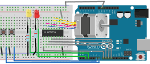 Pulling these pins HIGH will enable the motor, while pulling it LOW will disable the motor. When this jumper is in place, the 5V regulator is enabled, which derives the logic power supply (VSS) from the motor power supply (VS). Then, we also know that it is a four phase stepper motor since it had four coils in it. The A4988 is a micro-stepping driver for controlling bipolar stepper motors which have a built-in translator for easy operation. Stepper motors can turn an exact amount of degrees (or steps) as desired. It is safe to use the A4988 Driver without a heat sink if the current rating is up to 1A. A4988 Tutorial | Control NEMA17 Stepper Motor with A4988 Stepper Motor Driver Module & Arduino, Copyright 2022, All Rights Reserved | How To Electronics, Please consider supporting us by disabling your ad blocker, How to Control Stepper Motor with A4988 Driver & Arduino.
Yellow - Pin 10 Each channel of the module can deliver up to 2A to the stepper motor. Hi, The module has an on-board 5V regulator 78M05. Let us look at some of the important technical data obtained from the datasheet of this motor in the picture below. You can enter any desired values, like entering 1will make the motor to take only one step. Hello, I was wondering if it would be possible to power both the arduino and stepper motor (via the A4988) with a single power supply, instead of 2 (one 5V and one 12V). The sequence of pulses determines the spinning direction of the motor. DO you need to download the stepper.h file my code wont compile.
stepper example schrittmotor lectronique ingnierie radios elektromotor easydriver logiciel chipkit lu stepper arduino controlling circuitbasics Share the Joy of learning with us. Stepper stepper(STEPS, 8, 10, 9, 11); void setup() { 
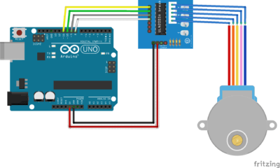
 On the Nano board, this 5v output is isolated from the 5v on the USB by means of a diode. Learn more, 1 small bipolar stepper Motor as shown in the image given below. The following image shows how to wire everything up. The correct wiring should be: To energise the four coils of the stepper motor we are using the digital pins 8,9,10 and 11.
Hey, thanks a lot! Finally in the loop section of the code, we simply call the step() function which makes the motor turn a specific number of steps at a speed set by the setSpeed() function.
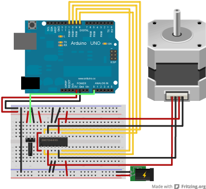
Now, upload the below program in your Arduino UNO and open the serial monitor. Another important data to notice is the Stride Angle: 5.625/64. There are lots of moving parts inside a printer, including motors. So you will be directed to NextPCB website. The circuit Diagram for the arduinostepper motor control project is shown above.
Now, to make the motor move one step we can use the following line. This is because of the gears that are connected between the motor and output shaft, these gears help in increasing the torque. The Driver module will have four LED using which we can check which coil is being energised at any given time.
Using this code, the stepper motor direction can be controlled. When the jumpers are in place, the motor is enabled. The methods described here can be used to infer how to use other motors and drivers which are not mentioned in this tutorial. If the wiring is correct, you will see the motor spins in the clockwise direction. The number of steps to be moved will be provided by the variable val. If the resistance is only a few ohms (<100), youve got a pair. The stepper motor is STOPPED Here, 360/11.25 = 32 steps per revolution. For example, if the Stepper Motor is rated for 350mA, we need to adjust the reference voltage to 0.14V.
A regular DC motor spins in only direction whereas a Stepper motor can spin in precise increments. { We appreciate it. At the center of the module is a big, black chip with a chunky heat sink the L298N, from ST Semiconductor. STEP input controls the micro-steps of the motor whereas DIR input controls the spinning direction of the motor. arduino stepper drv8825 potentiometer how2electronics 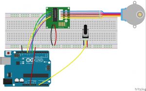 You can use it to power your Arduino or other circuitry that requires a 5V power supply. Submitted by sourajit das on Mon, 06/04/2018 - 19:06, Submitted by Michau on Wed, 07/04/2018 - 00:34, Everything work fine, but the questions is what about other variables?
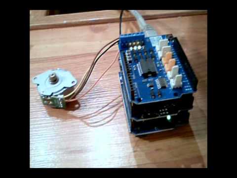
Pink/Purple - Pin 9 You can connect any 12-24V stepper motor to these terminals. Blue - Pin 8 You also need to keep both the ENA and ENB jumpers in place so that the motor is always enabled. stepper control arduino speed step code motor potentiometer lesson wiper analog diagram assignment week pot introduction kit servo category osoyoo You could. The EN pin is active low input, when pulled LOW the A4988 driver is enabled. Since we have 32 steps and 64 as the gear ratio we need to move 2048 (32*64=2048), to make one complete rotation. The 28BYJ-48 is a 5-wire unipolar stepper motor that runs on 5 volts and doesnt require any driver. It operates from 8 V to 35 V and can deliver up to approximately 1 A per phase without a heat sink or forced airflow. This means that the motor when operates in 8-step sequence will move 5.625 degree for each step and it will take 64 steps (5.625*64=360) to complete one full rotation. This motor has six wires, connected to two split windings. stepper interfacing 5v If you are planning on assembling your new robot, you will eventually want to learn how to control stepper motors. There is no technical reason for this motor for being named so; maybe we should dive much deeper into it. There are numerous varieties of stepper motors. The constructor of the Stepper class takes the steps per revolution of the motor and Arduino pin connections as arguments. In Arduino we will be operating the motor in 4-step sequence so the stride angle will be 11.25 since it is 5.625(given in datasheet) for 8 step sequence it will be 11.25 (5.625*2=11.25). // step one revolution in the other direction: Controlling a Stepper Motor With an HBridge, Identifying the Phases of a Bipolar Stepper Motor, Wiring a Bipolar Stepper Motor to the L298N Module and Arduino, Arduino Code - Controlling NEMA 17 Stepper Motor. A Stepper Motor is abrushless, synchronous motor which completesa full rotation into a number of steps.In this Arduino stepper motor tutorial we will learn about the most commonly available stepper motor 28-BYJ48 and how to interface it with Arduino using ULN2003 stepper motor module. Now lets connect the A4988 Stepper Motor driver to Arduino and control NEMA17 Stepper Motor.  Serial.begin(9600);
  We use a microcontroller like Arduino energize these coils in a particular sequence and make the motor perform the required number of steps. It looks like the speed can range between 0 to 1000 for 28-BYJ48 stepper motors. If you wish to control multiple stepper motors, it is recommended that you use a self-contained dedicated stepper motor driver such as the A4988. Please note: These are affiliate links. As you can see the motor has Unipolar 5-lead coil arrangement.
 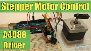 Submitted by Michael MacDonald on Tue, 03/06/2018 - 06:59, The circuit diagram is incorrect. However, it is always recommended that you consult the datasheets and guides of the motors and drivers specific to the models you have. In this tutorial we will Control the NEMA17 Stepper Motor with A4988 Driver Module & Arduino.
  The L298N motor driver actually has two input power pins VS and VSS.
IP22 rated medical & home-healthcare 18/24/36W AC-DC adaptors with interchangeable AC plugs. Why not using the Arduino 5V output to power the A4988 driver, instead of using another external 5V power source? However the amount of current supplied to the motor depends on the power supply of the system. All you need to know for now is that, to move a stepper motor, you tell it to move a certain number of steps in one direction or the other, and tell it the speed at which to step in that direction. 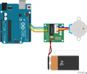
 For me is more difficult because, I can send only one parameter(one of them), Submitted by gvg on Tue, 07/24/2018 - 00:07. The speed can range between 0 to 200 for 28-BYJ48 stepper motors.
The Red wires will be supplied with +5V and the remaining four wires will be pulled to ground for triggering the respective coil.
The following animation shows how H-bridges drive a stepper motor. Read the line-by-line explanation in comment lines of code! As said earlier we will be using 4-step sequence method so we will have four steps to perform for making one complete rotation. If the wiring is correct, you will see the motor rotates clockwise direction. 
That is why most of the people trust NextPCB for PCB & PCBA Services. Arduino Stepper Motor Tutorial - Interfacing 28-BYJ48 Stepper Motor with Arduino Uno, AMF Series 18/24/36 W Medical AC-DC Adaptors, TPP 180 and TPI 180 Medical and Industrial AC/DC Power Supplies, NTS/NTU Series Reliable, Safe, and Durable DC-AC Pure Sine Wave Inverters, IsoMOV Series Hybrid Protection Component. The component purchase link is given as well. Serial.println(val); //for debugging For example, if you set the speed to, say, 1 RPM and called step(100) on a 100-step motor, this function will take a full minute to finish. The video which shows the sequence of energization can be found at the end of this tutorial. 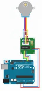 The frequency of the pulses determines the speed of the motor. Thanks for sharing, Submitted by Shahroz Shabbir on Tue, 10/31/2017 - 09:59. seems good (Y) and simple concept explained well. If you want to control the motor programmatically, you need to remove the jumpers and connect those pins to the digital pins on the Arduino. Share with your friends to help us spread the tutorial! Submitted by blue on Fri, 05/04/2018 - 19:49. Power Supply Pins: The pin include VDD & VMOT & Pair of GND pins.
  The motor is attached to digital pins 8 - 11 of Arduino. The PCB Board for the Nema17 Stepper Motor Control with A4988 & Arduino is designed using EasyEDA online Circuit Schematics & PCB designing tool.
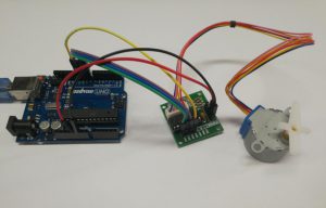
Once the connection is made the hardware should look something like this in the picture below. The L298N module has a total of 11 pins that connect it to the outside world. 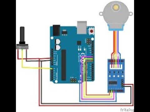
Stepper Motor can be controlled using the Arduino AccelStepper library. The motor will run back and forth with a speed of 200 steps per second and an acceleration of 30 steps per second.
Can you clarify what capacitor should be used for the 5v power supply? 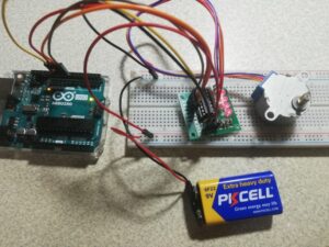 There are several ways to make a stepper motor stop: The below code make a stepper motor spin infinitely and stop immediately when a limit switch is touched. The front side and back side of the PCB is given below. Using the four control pins IN1, IN2, IN3 and IN4, you can control both the speed and the spinning direction of the stepper motor.
You will see the motor is stopped immediately, The result on Serial Monitor looks like below, The limit switch: TOUCHED The L298N motor driver has a supply range of 5V to 35V and is capable of supplying 2A continuous current per coil, so it works very well with most of our stepper motors.
Okay, so unlike a normal DC motor this one has five wires of all fancy colors coming out of it and why is it so?  Your email is safe with us, we dont spam. The direction -> ANTI-CLOCKWISE
stepper There are a many types of driver module and the rating of one will change based on the type of motor used. Put your multimeter in resistance mode and simply measure pairs of wires for their resistance. }, if (Serial.available()>0) If you buy the components through these links, We may get a commission at no extra cost to you. It is important to know how to calculate the steps per Revolution for your stepper motor because only then you can program it effectively. AccelStepper significantly improves on the standard Arduino Stepper library in several ways like it supports acceleration and deceleration. stepper uln2003 motor driver wire 5v phase Submitted by Pragati on Sat, 03/31/2018 - 19:31. arduino motor stepper control uno Thank you! The following are the components required for learning this tutorial. That is the reason of using the driver circuit. You can simply download the Gerber File and order the PCB from https://www.nextpcb.com/. (adsbygoogle = window.adsbygoogle || []).push({}); The A4988 is a complete Microstepping Motor Driver with a built-in translator for easy operation. arduino projects stepper motor electronics engineering diy The Arduino Nano will accept 12v on the Vin pin and produce 5v on the 5v pin via the onboard regulator. This is where the stepper motors come in handy. The Stepper Motors therefore are manufactured with steps per revolution of 12, 24, 72, 144, 180, and 200, resulting in stepping angles of 30, 15, 5, 2.5, 2, and 1.8 degrees per step. All rights reserved. We can connect any bipolar stepper motor having voltages between 8V to 35 V to those pins.
By setting appropriate logic levels to those pins we will set the motors to at least one of the five-step resolutions. Each phase draws 1.2 A at 4 V, allowing for a holding torque of 3.2 kg-cm. NEMA 17 Stepper motor is generally used in Printers, CNC machines and Laser Cutters. Now you can visit the NextPCB official website by clicking here: https://www.nextpcb.com/. BUT :5v is very low and you will need more current. Now imagine a printer. arduino stepper tb6600 Even very slow speeds are also supported. I think about setSpeed, moveTo, setAcceleration, setMaxSpeed or clockwise. Submitted by muditha on Thu, 04/26/2018 - 09:19. my stepper motor not working anti click wise. There are four coils which have to be energized in a particular sequence. stepper lesson We took a lot of time and effort to create the content of this tutorial, please respect our work!
One such motor acts as the paper feed, spinning rollers that move the piece of paper as ink is being printed on it. NEMA 17 is a hybrid stepping motor with a 1.8 step angle (200 steps/revolution). Next you have to create instances in which we specify the pins to which we have connected the Stepper motor. More voltage helps in using thinner wires in circuit and so keep it cooler.
Because of the excessive power dissipation of the A4988 driver, there is a rise of temperature that can go beyond the capacity of IC, probably damaging it. If you are planning to build your own 3D printer or CNC machine then you will need to control a bunch of stepper motors. Also remember to connect the Ground of the Arduino with the ground of the Diver module. I had it wired how you have it in the diagram and ran the code and it does nothing. #define STEPS 32. We can do that by adjusting the reference voltage using the potentiometer on the board and considering this equation below. These motors have a sequence of coils present in them and these coils have to be energized in a particular fashion to make the motor rotate. Thus, we can control the stepper motor with just 2 pins from our controller. The other two wires should form the second pair. You can leave the jumper in place if the motor power supply is less than 12V. The number of pulses determines how far the motor will turn. Small current from Arduino becomes big current for the motor. We are considering to make the video tutorials. Most stepper motors will operate only with the help of a driver module. The limit switch: TOUCHED I used D2 & D3 pins to control the motor direction and step. SLP Pin is active low input. To rotate in anti-clockwise just enter the number with negative sign. 

 Pulling this pin LOW puts the driver in sleep mode, minimizing the facility consumption. This helped me to understand the working of the stepper as well as the coding for the same. You will see the stepper motor's direction is changed to the anti-clockwise, You will see the stepper motor's direction is changed to clockwise, The limit switch: TOUCHED
We also offer ideas and solutions for students, organizations and Industries and also provide them with the required training in different fields. Black, Yellow, Green wires are part of the first winding while Red, White, and Blue is part of the second winding.
The primary principle for all driver modules will be to source/sink enough current for the motor to operate. In this tutorial we are going to write the arduino stepper motor code and for that we willprogram the Arduino in such a way that we can enter the number of steps to be taken by the stepper motor through the serial monitor of the Arduino. If you have any doubts post them on the comment section below our on our forums., #include