centrifugal impellers endobj
0000010517 00000 n
Then deduct the velocity pressure from the atmospheric pressure (p = p - p), p: Multiply atmospheric pressure by 1.025 (i.e. It is important to ensure that the impeller aspect ratio and diffuser inlet area is always larger than this to minimise frictional loss. A simple calculation procedure you may use to establish the output flow rate of the fan (impeller inside a casing) is provided in the calculators technical help menu. To produce the required results of removing saturated air, custom industrial blowers created that corrosion and rust resistant, which suggests the utilization of chrome steel or metals coated in an exceedingly wet resistant epoxy. impeller speed: N = 2685 {RPM}
tM/ym}Ifu"++Z\N This problem can be overcome simply by altering the outlet angle to 89.99. p = 103858N/m). 0
0.67) or a percentage value (e.g. 0000007178 00000 n
Because power is calculated thus: P = 2..N.T and T = m.g.r, that required to spin your impeller can be linearly interpolated by factoring in the mass of the impeller. Centrifugal: = 74.4%; H = 14.3m; P = 322W; p = 181Pa
Even forward facing blades should have inlet angles <90 {'forward facing' refers to the outlet angle only}, is the angle of the outlet tip of the blade which can only be between 0 and 180. centrifugal calculations  ?Rji~fhx*tbqIx/)FTp`F0of"3R
7v9oN'PWN6JUv6>0R7F. 3 0 obj
2) play with the outside tip angle until you achieve reasonable results,
In little and encircled workspaces wherever paint and vapours accumulate, industrial blowers serve the aim of removing and filtering the fumes and vapours for the clean air.
?Rji~fhx*tbqIx/)FTp`F0of"3R
7v9oN'PWN6JUv6>0R7F. 3 0 obj
2) play with the outside tip angle until you achieve reasonable results,
In little and encircled workspaces wherever paint and vapours accumulate, industrial blowers serve the aim of removing and filtering the fumes and vapours for the clean air. 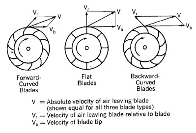 The outlet area may be larger or smaller than this dependent upon your performance requirements.
Whilst a fan's efficiency is not the only consideration for a designer, performance being his/her primary concern, it should not be ignored. However, if the width of your casing outlet is narrower than the impeller, your fan's efficiency will suffer. 2 0 obj 0000001525 00000 n centrifugal compressor pump compressors impeller fans pumps analysis thermodynamic problems example fan axial fans vane flow figure overloading non cibse ventilation ducted module systems cibsejournal source Efficiency varies slightly with impeller diameters ( and ) and operating speed (N) but not with fan length (). If you just alter the outlet angle without adjusting the inlet angle you will struggle to find a solution. Such impellers provide greater flow rates but reduced pressure potential, Centrifugal fans are normally fitted with impeller aspect ratios greater than 0.5, Axial fans are normally fitted with impeller aspect ratios less than 0.5 (where flow is of greater importance than pressure). Please bear in mind that the backward-straight-forward relationship refers to the inlet tip of the impeller blade (0 < < 180)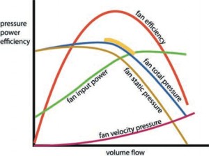 0000006629 00000 n
0000085583 00000 n
0000006629 00000 n
0000085583 00000 n
Therefore, the cross-sectional area of the inlet diffuser should be no less than that of the impeller blade inlet. 3) fettle both tip-angles (inside and outside) to finalise your results.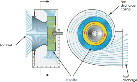 %PDF-1.5
your fan will not actually achieve the desired/calculated flow-rate and/or pressure. centrifugal blowers blower compressor air drawing facts fast power stage Blowers for heavy sorts of operations product should be of exceptionally durable materials and capable of putting up with the severe abuse from removing the chips, particles, and granular residue.
%PDF-1.5
your fan will not actually achieve the desired/calculated flow-rate and/or pressure. centrifugal blowers blower compressor air drawing facts fast power stage Blowers for heavy sorts of operations product should be of exceptionally durable materials and capable of putting up with the severe abuse from removing the chips, particles, and granular residue.
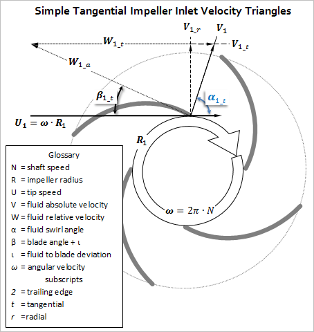
startxref Too few blades; the air trailing each blade will be turbulent, reducing operational efficiency. It is inadvisable to significantly orientate the outlet tip of an impeller blade in a forward direction ( > 110) as it would disrupt airflow and give unreliable results. centrifugal impeller calculations blowers crank portion T is the torque required to rotate the blades through the air at the speed (N) required for a free-flowing impeller. This value is zero for axial fans and sometimes ignored in head (H) and efficiency () calculations for centrifugal fans. `Qf#Ywcl#3#mFo CND^NG'ku9,KC1nC=@Ql 9t rvHiQ}n+_. p = p .v. {use '+' if the direction of movement is towards the fan and '-' if it is moving away from the fan}, Velocity Pressure; is the pressure generated by the gas moving through the fan, Discharge Pressure; is the sum of the velocity pressure and the difference between the outlet pressure and the inlet pressure (Fig 2), Static Pressure; is the maximum of the inlet and outlet pressures, Pressure Head; is the head generated by the discharge pressure at the outlet side of the fan, The shape of your blades and the direction they travel will define the performance characteristics of your fan. 482 39 centrifugal impeller tangential 2) Paddle blades must be 90 inlet and outlet (not simply close to this value) as they do not drive the air using the blade profile, they drive air out through the impeller using centrifugal force and any other angle will create unnecessary back pressure, 3) Always use inlet blade angles considerably less than 90.
xref
The leading (inlet edge) angle can be set to eliminate this shock resulting in v=0. Centrifugal blowers have a gear system and may have one or multiple stage construction.
blade inlet angle: = 78.5 (79) {} # %PDF-1.4 %
The fan calculator converts this value into mass flow rate {Q}, mole flow rate {Q} and linear velocity {v}. The aim and performance of business blowers is to be a permanent addition to a space to extend air flow and take away contaminants, dust, dirt, and particulate. The expected efficiency is about 0.58. v and v: the centrifugal velocity component of the air will be zero for the inlet edge of an axial fan blade and will vary from inlet to outlet for both axial and centrifugal fans 0000002000 00000 n This flow rate is possible. 0000010481 00000 n
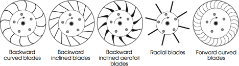
The following table summarises the characteristics you can expect from your fan dependent upon the shape of its blades (Fig 3).
Even forward facing blades should have inlet angles <90 {'forward facing' refers to the outlet angle only}, Fig 7. Blade balancing is easier to achieve than one blade designs. this pressure only exists in the moving gas, pd is the discharge pressure generated by the fan; i.e. You need not concern yourself with pressures lower than 1 bar as flow rates under such conditions will be achieved with less power input. Please correct the marked field(s) below. volute centrifugal scirp 5 Blades: Best configuration for all medium aspect ratio impellers. stream You will find that some changes to input data reduce one loss but raise another so a little trial and error is required to maximise efficiency. the maximum of inlet and outlet pressure, h is the pressure head of the gas at the outlet side of the fan, V is the volume change rate of the room volume (V).
Output co-ordinates can be found in the Data Listing menu. <> multistage centrifugal lamson exhauster blowers If you need to include losses in addition to the efficiency of the fan () you can incorporate them by multiplying the expected additional losses by the efficiency factor and entering the modified value for in the input data, Q is the mass flow rate of gas through the fan, Q is the mole flow rate of gas through the fan, v is linear velocity of the gas through the outlet aperture, and are the input and output densities of the gas (respectively) passing through the fan, p is the velocity pressure of the gas passing through the fan, i.e. A comparison between the efficiency and performance of equivalent Axial and Centrifugal impellers is provided below air density at impeller inlet: = 1.2 {kg/m}
each fan in the sequence increases pressure over the previous fan until you have achieved the pressure required. This calculator is suitable as a close approximation (see Accuracy below) calculation tool for any and all extraction and compression calculations in atmospheric and/or ducting systems. 2) Use Fans to size your impeller and set your blade angles. hXmo6+bd +,|!E"9u(3)y`I%G (%CD+!r` -8,jc4#809Tj"9QJEFZeXh#F*%:K-9W^?Sx'us)l[y!I"daW_ y[?'sTT6(~RB3K45pLayu~ an\UuC:M27U}{yK5lzGysp|`gQ+=//jEU~:uU5O;*XY\7]HJf:'YE(Bu]2vEgCX8pe`M=-/dQ\5w%L5iJp|O10}.? Raise to improve efficiency (), Centrifugal Fans 0000010741 00000 n The two calculation examples in Fig 8 both took the same time to reproduce (5-minutes), but the backward-blade calculation was easier to match in the time allotted. %PDF-1.5 % 730 0 obj <> endobj 0000010331 00000 n 0000008372 00000 n You should therefore apply the relevant performance specification of your preferred supplier's product to your final design as opposed to your design requirements. endstream endobj 519 0 obj<>/Size 482/Type/XRef>>stream
1 Blade: Airflow will occur according to our calculations for about 1/3rd of the impeller volume, the rest of the air within the impeller will be turbulent making your fan extremely inefficient. : raises L and lowers L Mechanical/electrical efficiency must be dealt with by the designer when selecting suitable materials and drive systems. a fan), P is the power required to drive the torque (T), p is the change in pressure from inlet to outlet, is the density of the air leaving the fan, H is the pressure-head of the fan before removing the effect of the operational losses (L, L, L). In order to lower Industrial dirt loading units move air and contaminants through a system that captures, collects, and removes dangerous particles.
v and v: the inlet and outlet velocities of the air through the blades will be the same for axial fans and different for centrifugal fans This value is equal to 'v' in axial fans, v is the axial (AXIAL FANS) or radial (CENTRIFUGAL FANS) velocity of the air at the outlet edge of the blades.
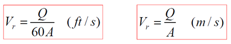
It is therefore necessary to play with these to achieve the desired results. it is entirely up to you as to how many blades you use in your impeller. 520 0 obj<>stream endobj In order to improve the airflow efficiency of a fan, you need to minimise the losses (L, L, L) and to do this you need to optimise the size and shape of the its blades. For general applications, maximum isentropic efficiency will be achieved by selecting small inlet angles and large outlet angles, however, this will be at the expense of head efficiency. Too many blades will also reduce fan efficiency through increased skin friction and impeller mass (i.e. This value is equal to 'v' in axial fans, v is the velocity of the air passing over the blades at the inlet edge of the blades, v is the velocity of the air passing over the blades at the outlet edge of the blades, v is the rotational velocity component of the air at the inlet edge of the blades (this value is zero for axial fans), v is the rotational velocity component of the air at the outlet edge of the blades, A is the airflow area through the blades of an axial impeller, Ar is the ratio of inlet and outlet areas (Ai:Ao), Ai is the airflow inlet area through the blades of a centrifugal impeller, Ao is the airflow outlet area through the blades of a centrifugal impeller. As shown in Fig 5, except for very specific performance requirements, there is little to be gained in designing a centrifugal impeller with blade tip angles greater than 90. 0000085441 00000 n the lower the air resistance, the faster the rotation and the greater the flow. impeller centrifugal blower displacement calculations positive where It is now considered to be the industry standard and has stood the test of time since 1916. fan centrifugal fans induced draft blower software boiler air package industrial based blowers cloud type duct interested indiamart kolkata Fans will not generate a result for forward facing configurations with insufficient blades. air) passing through the fan, p and p are pressures of the gas at the inlet and outlet sides of the fan respectively, is temperature of the gas at both the inlet and outlet sides of the fan, P is the minimum power of the fan (e.g. v and v: the absolute velocity of the air at the inlet and outlet edges of the blade and will vary from inlet to outlet for both axial and centrifugal fans. set to {} for L = 0 Selecting the correct values for inlet and outlet pressures will provide your greatest dilemma in these calculations. When planning the design of a centrifugal fan, it is important that you begin by selecting the most suitable blade type for your purposes. You may enter this value as a factor (e.g. Industrial blowers are either centrifugal, axial, or positive displacement. velocity impeller pump centrifugal triangle head triangles engineering twist inlet outlet density independent liquid mechanical come formula populer stackexchange theoretical As long as the cross-sectional area of a fan's diffuser (outer casing; Ac) is greater than the surface area of the outside diameter of the impeller (A or Ao for axial and centrifugal respectively), the fan will exhaust 100% of volumetric flow with the same pressure variation as generated by the impeller (p). 0000004382 00000 n endstream endobj 731 0 obj <>/Metadata 50 0 R/Outlines 113 0 R/PageLayout/OneColumn/Pages 728 0 R/StructTreeRoot 120 0 R/Type/Catalog>> endobj 732 0 obj <>/Font<>>>/Rotate 0/StructParents 0/Type/Page>> endobj 733 0 obj <>stream making the axial fan more efficient, primarily due to the negligible losses from shock and outlet energy that are always present and need to be optimised in centrifugal fans. if you don't follow the rules, your fan won't work. These extremely technical devices designed to supply higher pressure at a quantitative relation of one1.1 to 1.2. but all of them will shift gases at the same rate based upon the input power. For the purposes of this description; the inlet area of a diffuser is the orifice nearest (adjacent) to the impeller. calculations centrifugal As can be seen in Fig 8; the following input data produces comparable results with a data-sheet issued by a prominent manufacturer for one of its fans: Fig 2 shows the pressures through a fan, each of which is described below: Inlet Pressure; is the static pressure on the inlet side of the fan. ratio of specific heats (cp/cv) {air: = 1.4226}: = 1.4226 I.e. L is the loss of head from the stored energy in the air leaving the fan. For a few industries, dirt assortment is necessary a part of their operations, also as being legal. This specific speed value corresponds to the centrifugal impeller. A fan casing may be any shape or size as long as its inlet and outlet diffusers do not impede airflow beyond that intended by the designer.
number of blades in the impeller: n = 40 1) Always try to use a backward facing blade where possible.
Industrial blowers give high and even air flow through the ductwork of a building. This has a higher speed value efficiency. In order to lower The fan calculator addresses only the blade angles. endstream endobj 483 0 obj<>/Metadata 66 0 R/PieceInfo<>>>/Pages 65 0 R/PageLayout/OneColumn/OCProperties<>/StructTreeRoot 68 0 R/Type/Catalog/LastModified(D:20080724221907)/PageLabels 63 0 R>> endobj 484 0 obj<>/PageElement<>>>/Name(HeaderFooter)/Type/OCG>> endobj 485 0 obj<>/ColorSpace<>/Font<>/ProcSet[/PDF/Text/ImageB/ImageC/ImageI]/Properties<>/ExtGState<>>>/Type/Page>> endobj 486 0 obj[487 0 R] endobj 487 0 obj<>/A 515 0 R/H/I/StructParent 1/Border[0 0 0]/Type/Annot>> endobj 488 0 obj<> endobj 489 0 obj<> endobj 490 0 obj[/Indexed 507 0 R 255 516 0 R] endobj 491 0 obj<> endobj 492 0 obj<> endobj 493 0 obj<> endobj 494 0 obj<> endobj 495 0 obj<>stream x=ksUy\P/G-,\r `C$CB_=J.Iv=5zh4_05fZnqZ\:Z6MBw]V-\-Z{} Lb{u3]\or_{ Now with the help of an example, we will understand impeller speed of air blower: = 0 Ze (we are dealing with air, so elevation head is negligible compared with pressure and velocity heads). The minor differences are due to the lack of information available, such as blade angles and atmospheric properties, in the data-sheet concerned.
The greater the outlet blade angle the shallower must be the inlet tip angle. Moreover, a one-degree variation in blade tip angle will effect fan performance differently whether it is applied to the inner or outer edge of the blade. I.e. Friction (L): The air passing over the surface of the blade (v to v) will slow down as a result of friction between the air and blade. This value is zero for axial fans. propeller Since several chemical in these applications is flammable, exhaust industrial blowers ought to be spark resistant. However:
0000003743 00000 n greater operational power). Atmospheric pressure normally varies between 0.98 & 1.05 bar. 2 Blades: Significantly improved airflow characteristics than one blade designs but still generates significant turbulence (behind each blade). The ninety-nine potency of the system guarantees that each one of harmful odours, contaminants, and gas fumes are removed. gravitational acceleration: g = 9.80663139 {m/s} However, by charging the fan with air, it will naturally generate a localised vacuum at the inlet side, and the greater movement of air outside the fan will normally generate higher positive pressure than atmospheric for the fan to overcome. The fumes and alternative contaminants removed by scrubbers or points of emission. centrifugal sciencedirect fan centrifugal blades blade types blower curved backward forward fans impellers figure 240z ventilation 1972 both cibsejournal dust Watts). 1 0 obj However, the results are sufficient to validate Charles Innes' theory, on which Fans is based. N: raises L and L
Differences such as efficiency or flow rate occur in the type of fan due to particular design advantages that favour one characteristic over another. If this angle is less than '' a warning will appear to increase its value, is the length of the blades between the inlet and outlet edges in an axial fan, w is the width of the blades in a centrifugal fan, parallel to the axis of rotation of the impeller, is the density of the air at the inlet edge of the fan blades, p is the pressure of the air at the inlet edge of the fan blades, T is the temperature of the air at the inlet edge of the fan blades, R is the specific (or mass) gas constant, F is the coefficient of friction of air (with the blades).
blade outlet angle: = 134.6 (41) {} # lateral channel blowers absolute assembled impeller rotating balanced dynamically ensure shaft directly almost motor parts gugliotta 0000000016 00000 n You should be careful when selecting your units as your gas constant (R) will dictate the units of mass and length for all your output results, i.e. xb```b``Sa`c`gd@ AV(GL)a*k%00lq C,F$KE,0y-=7Iec axial fans) and much simpler to balance than 1 and 2-Blade designs.
They do this by rotating a series of angled blades (or vanes) that pull the air through an aperture. In this case, the outlet area should be no less than that of the impeller blades. 0000001097 00000 n # blade angles: forward facing (backward facing).
4) Input area of the impeller blades is ..w 482 0 obj <> endobj The head losses generated by the blade tip angles (inlet and outlet) define a fan's 'air' efficiencies. You can include this effect if you wish by using the following formula: 0000011380 00000 n The results are not exact because the blade angles, air properties and constants used by the manufacturer are unknown. air) from one place to another for extraction, air-conditioning, compression, etc. you cannot have a factor>1.0 and Fans will assume that your fan will have an efficiency greater than 1%.
Such a configuration is also difficult to balance. it is advisable to minimise the number of blades in high flow-rate fans. This value must be set to 1 (one) if p is in units of mass per unit area such as kgf/m or lbf/ft. However, the flow rate in wide high aspect ratio impellers can be improved by matching the shape of the input orifice to that of the impeller's cross-section, The radial depth of a medium aspect ratio (0.5<<0.75) impeller is relatively high compared with its OD. Increasing the input blade-tip angle () will increase power consumption (P) and pressure variation (p), but it will decrease flow rate (Q) Axial fans only operate with inlet and outlet angles between 0 and 90 and the outlet angle must be greater than the inlet angle (Fig 3). specific gas constant (air): R = 283.5383565 {J/K/kg} LTD. - WATER TREATMENT COMPANY DELHI/NCR, J-176, SECTOR-41, NOIDA, Gautam Buddha Nagar, Uttar Pradesh,India, 201301. Fans' calculations are based upon all the entrained air passing through the impeller with each rotation, which is normal practice for optimum blade configurations.
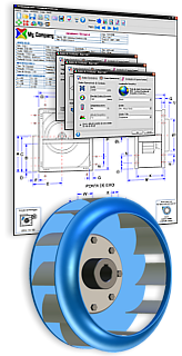
fan software centrifugal calculations industrial cad organized establishes requirements flexible highly environment friendly analysis user
0000012104 00000 n L=0 blowers calculation evpvacuum vacuum kq2 formula Dust loading industrial blowers collect dirt to boost air quality. As mentioned above, there are pros and cons for each configuration; pressure, flow, efficiency, noise, etc. Outlet blade angles greater than 90 will always give you a bit of a challenge to create a workable solution. rotodynamic pumps diffuser impeller volute discharge flow stage pressure piping increasing further direct another system into You should use 89.5 or 90.5 for such an angle. The secret here is to ensure that inlet angle is very shallow (e.g. For example; an impeller of 0.5m diameter with an ID of 0.1m will never achieve the flow rate for which the impeller OD is capable unless the inlet pressure/flow-rate is artificially increased. These values have therefore been estimated for the Fans calculation.
Multi-stage fans are used where a very high outlet pressure is required. v and v: the circular speed of the inlet and outlet edges of the blade will be the same for axial fans and different for centrifugal fans One normal axial fan operating at maximum efficiency can achieve a velocity pressure (p) of up to 0.5psi (3,500N/m). endobj See Calculations above.
Optimum efficiencies (head and isentropic) generally occur when inlet and outlet blade tips are set at angles around 45. CalQlata defines the aspect ratio () of an impeller thus: = ID/OD, The radial depth of a high aspect ratio (0.75<<1.0) impeller is relatively shallow compared with its OD, High aspect ratio impellers are used for high-pressures and low flow rates (small impeller volume). centrifugal blower animation fan fans inline radial rebel duct quiet powerful 0000005758 00000 n For example; Fans does not consider the manufacturing quality of the impeller casing, nor does it consider internal bends or deformations affecting the flow-path. impeller outside diameter: = 0.16 {m} L is the loss of head due to the air changing direction as it enters the fan. Note: excessive blade angles in backward facing blades will quickly cause any fan (and its calculations) to fail; forward facing blade configurations are far more robust. fan pressure speed diameter impeller organ centrifugal blower vs benchmark fig1 vertical scale
0000002654 00000 n <> 0000092243 00000 n You will find values for the appropriate constants (R and g) in the Technical Help menu of the fan calculator. 0000006136 00000 n Whilst it can be difficult to recalculate a manufacturer's working fan if most of the input data is unknown, it can be reproduced by playing with the blade tip angles ( & ). 1.05 bar represents unusually high pressure and may be ignored for general applications.
Shock (L): The air entering a centrifugal impeller changes direction from v to v producing a shock load on the blade. 0000014774 00000 n v and v: the speed of the air over the surface of the blade will vary from inlet to outlet for both axial and centrifugal fans impeller width: w = 0.0616 {m} It is usual to ensure that the inlet and outlet areas of the casing are the same as the inlet and outlet areas of the impeller. Saturated air contains wet or gases. Air movement is achieved by massive angle blades connected to the hub of the blower. A little bit of advice; follow the sequence below; The only variables that need to be modified in a fan to improve its efficiency are listed below: Axial Fans 0000003299 00000 n Irrespective of design criteria, an impeller's aspect ratio should ensure that its airflow is not compromised. If this angle is greater than '' a warning will appear to increase the outlet angle For example: <]>> hb```f``jc`a``d@ A+s\ageee:1g$ \;viSG.oT"b'frvfL;qCGrGGGdHdG@vH 8X$AQm##7K-|v@L.sqKMa(qAa L=0 endstream endobj startxref There are a number of fan types: impeller, axial, centrifugal, Sirocco, etc. Unless the purpose of a fan is to generate suction, there is nothing to be gained by restricting inlet airflow. 0000002157 00000 n You may use any units you like, but you must be consistent. This should also include the velocity pressure on the inlet side (if known) that is constant and in-line with the fan.
0000009002 00000 n Apart from the electrical and mechanical components, the efficiency of a fan is to a large extent dependent upon the shape and orientation of the blades. Power will increase with material mass & drive mechanism inefficiencies, and the head and flow rates will vary with casing design. Efficiency value is not maximum.
770 0 obj <>stream 6 Blades: Losses from increased skin friction and mass begin to exceed airflow gains. It is normal practice to design the diffuser outlet to minimise airflow restriction.
 ?Rji~fhx*tbqIx/)FTp`F0of"3R
7v9oN'PWN6JUv6>0R7F. 3 0 obj
2) play with the outside tip angle until you achieve reasonable results,
In little and encircled workspaces wherever paint and vapours accumulate, industrial blowers serve the aim of removing and filtering the fumes and vapours for the clean air. The outlet area may be larger or smaller than this dependent upon your performance requirements.
?Rji~fhx*tbqIx/)FTp`F0of"3R
7v9oN'PWN6JUv6>0R7F. 3 0 obj
2) play with the outside tip angle until you achieve reasonable results,
In little and encircled workspaces wherever paint and vapours accumulate, industrial blowers serve the aim of removing and filtering the fumes and vapours for the clean air. The outlet area may be larger or smaller than this dependent upon your performance requirements. Whilst a fan's efficiency is not the only consideration for a designer, performance being his/her primary concern, it should not be ignored. However, if the width of your casing outlet is narrower than the impeller, your fan's efficiency will suffer. 2 0 obj 0000001525 00000 n centrifugal compressor pump compressors impeller fans pumps analysis thermodynamic problems example fan axial fans vane flow figure overloading non cibse ventilation ducted module systems cibsejournal source Efficiency varies slightly with impeller diameters ( and ) and operating speed (N) but not with fan length (). If you just alter the outlet angle without adjusting the inlet angle you will struggle to find a solution. Such impellers provide greater flow rates but reduced pressure potential, Centrifugal fans are normally fitted with impeller aspect ratios greater than 0.5, Axial fans are normally fitted with impeller aspect ratios less than 0.5 (where flow is of greater importance than pressure). Please bear in mind that the backward-straight-forward relationship refers to the inlet tip of the impeller blade (0 < < 180)
 0000006629 00000 n
0000085583 00000 n
0000006629 00000 n
0000085583 00000 n
Therefore, the cross-sectional area of the inlet diffuser should be no less than that of the impeller blade inlet. 3) fettle both tip-angles (inside and outside) to finalise your results.
%PDF-1.5
your fan will not actually achieve the desired/calculated flow-rate and/or pressure. centrifugal blowers blower compressor air drawing facts fast power stage Blowers for heavy sorts of operations product should be of exceptionally durable materials and capable of putting up with the severe abuse from removing the chips, particles, and granular residue. 
startxref Too few blades; the air trailing each blade will be turbulent, reducing operational efficiency. It is inadvisable to significantly orientate the outlet tip of an impeller blade in a forward direction ( > 110) as it would disrupt airflow and give unreliable results. centrifugal impeller calculations blowers crank portion T is the torque required to rotate the blades through the air at the speed (N) required for a free-flowing impeller. This value is zero for axial fans and sometimes ignored in head (H) and efficiency () calculations for centrifugal fans. `Qf#Ywcl#3#mFo CND^NG'ku9,KC1nC=@Ql 9t rvHiQ}n+_. p = p .v. {use '+' if the direction of movement is towards the fan and '-' if it is moving away from the fan}, Velocity Pressure; is the pressure generated by the gas moving through the fan, Discharge Pressure; is the sum of the velocity pressure and the difference between the outlet pressure and the inlet pressure (Fig 2), Static Pressure; is the maximum of the inlet and outlet pressures, Pressure Head; is the head generated by the discharge pressure at the outlet side of the fan, The shape of your blades and the direction they travel will define the performance characteristics of your fan. 482 39 centrifugal impeller tangential 2) Paddle blades must be 90 inlet and outlet (not simply close to this value) as they do not drive the air using the blade profile, they drive air out through the impeller using centrifugal force and any other angle will create unnecessary back pressure, 3) Always use inlet blade angles considerably less than 90.
xref
The leading (inlet edge) angle can be set to eliminate this shock resulting in v=0. Centrifugal blowers have a gear system and may have one or multiple stage construction.
blade inlet angle: = 78.5 (79) {} # %PDF-1.4 %
The fan calculator converts this value into mass flow rate {Q}, mole flow rate {Q} and linear velocity {v}. The aim and performance of business blowers is to be a permanent addition to a space to extend air flow and take away contaminants, dust, dirt, and particulate. The expected efficiency is about 0.58. v and v: the centrifugal velocity component of the air will be zero for the inlet edge of an axial fan blade and will vary from inlet to outlet for both axial and centrifugal fans 0000002000 00000 n This flow rate is possible. 0000010481 00000 n
The following table summarises the characteristics you can expect from your fan dependent upon the shape of its blades (Fig 3).
Even forward facing blades should have inlet angles <90 {'forward facing' refers to the outlet angle only}, Fig 7. Blade balancing is easier to achieve than one blade designs. this pressure only exists in the moving gas, pd is the discharge pressure generated by the fan; i.e. You need not concern yourself with pressures lower than 1 bar as flow rates under such conditions will be achieved with less power input. Please correct the marked field(s) below. volute centrifugal scirp 5 Blades: Best configuration for all medium aspect ratio impellers. stream You will find that some changes to input data reduce one loss but raise another so a little trial and error is required to maximise efficiency. the maximum of inlet and outlet pressure, h is the pressure head of the gas at the outlet side of the fan, V is the volume change rate of the room volume (V).
Output co-ordinates can be found in the Data Listing menu. <> multistage centrifugal lamson exhauster blowers If you need to include losses in addition to the efficiency of the fan () you can incorporate them by multiplying the expected additional losses by the efficiency factor and entering the modified value for in the input data, Q is the mass flow rate of gas through the fan, Q is the mole flow rate of gas through the fan, v is linear velocity of the gas through the outlet aperture, and are the input and output densities of the gas (respectively) passing through the fan, p is the velocity pressure of the gas passing through the fan, i.e. A comparison between the efficiency and performance of equivalent Axial and Centrifugal impellers is provided below air density at impeller inlet: = 1.2 {kg/m}
each fan in the sequence increases pressure over the previous fan until you have achieved the pressure required. This calculator is suitable as a close approximation (see Accuracy below) calculation tool for any and all extraction and compression calculations in atmospheric and/or ducting systems. 2) Use Fans to size your impeller and set your blade angles. hXmo6+bd +,|!E"9u(3)y`I%G (%CD+!r` -8,jc4#809Tj"9QJEFZeXh#F*%:K-9W^?Sx'us)l[y!I"daW_ y[?'sTT6(~RB3K45pLayu~ an\UuC:M27U}{yK5lzGysp|`gQ+=//jEU~:uU5O;*XY\7]HJf:'YE(Bu]2vEgCX8pe`M=-/dQ\5w%L5iJp|O10}.? Raise to improve efficiency (), Centrifugal Fans 0000010741 00000 n The two calculation examples in Fig 8 both took the same time to reproduce (5-minutes), but the backward-blade calculation was easier to match in the time allotted. %PDF-1.5 % 730 0 obj <> endobj 0000010331 00000 n 0000008372 00000 n You should therefore apply the relevant performance specification of your preferred supplier's product to your final design as opposed to your design requirements. endstream endobj 519 0 obj<>/Size 482/Type/XRef>>stream
1 Blade: Airflow will occur according to our calculations for about 1/3rd of the impeller volume, the rest of the air within the impeller will be turbulent making your fan extremely inefficient. : raises L and lowers L Mechanical/electrical efficiency must be dealt with by the designer when selecting suitable materials and drive systems. a fan), P is the power required to drive the torque (T), p is the change in pressure from inlet to outlet, is the density of the air leaving the fan, H is the pressure-head of the fan before removing the effect of the operational losses (L, L, L). In order to lower Industrial dirt loading units move air and contaminants through a system that captures, collects, and removes dangerous particles.
v and v: the inlet and outlet velocities of the air through the blades will be the same for axial fans and different for centrifugal fans This value is equal to 'v' in axial fans, v is the axial (AXIAL FANS) or radial (CENTRIFUGAL FANS) velocity of the air at the outlet edge of the blades.
It is therefore necessary to play with these to achieve the desired results. it is entirely up to you as to how many blades you use in your impeller. 520 0 obj<>stream endobj In order to improve the airflow efficiency of a fan, you need to minimise the losses (L, L, L) and to do this you need to optimise the size and shape of the its blades. For general applications, maximum isentropic efficiency will be achieved by selecting small inlet angles and large outlet angles, however, this will be at the expense of head efficiency. Too many blades will also reduce fan efficiency through increased skin friction and impeller mass (i.e. This value is equal to 'v' in axial fans, v is the velocity of the air passing over the blades at the inlet edge of the blades, v is the velocity of the air passing over the blades at the outlet edge of the blades, v is the rotational velocity component of the air at the inlet edge of the blades (this value is zero for axial fans), v is the rotational velocity component of the air at the outlet edge of the blades, A is the airflow area through the blades of an axial impeller, Ar is the ratio of inlet and outlet areas (Ai:Ao), Ai is the airflow inlet area through the blades of a centrifugal impeller, Ao is the airflow outlet area through the blades of a centrifugal impeller. As shown in Fig 5, except for very specific performance requirements, there is little to be gained in designing a centrifugal impeller with blade tip angles greater than 90. 0000085441 00000 n the lower the air resistance, the faster the rotation and the greater the flow. impeller centrifugal blower displacement calculations positive where It is now considered to be the industry standard and has stood the test of time since 1916. fan centrifugal fans induced draft blower software boiler air package industrial based blowers cloud type duct interested indiamart kolkata Fans will not generate a result for forward facing configurations with insufficient blades. air) passing through the fan, p and p are pressures of the gas at the inlet and outlet sides of the fan respectively, is temperature of the gas at both the inlet and outlet sides of the fan, P is the minimum power of the fan (e.g. v and v: the absolute velocity of the air at the inlet and outlet edges of the blade and will vary from inlet to outlet for both axial and centrifugal fans. set to {} for L = 0 Selecting the correct values for inlet and outlet pressures will provide your greatest dilemma in these calculations. When planning the design of a centrifugal fan, it is important that you begin by selecting the most suitable blade type for your purposes. You may enter this value as a factor (e.g. Industrial blowers are either centrifugal, axial, or positive displacement. velocity impeller pump centrifugal triangle head triangles engineering twist inlet outlet density independent liquid mechanical come formula populer stackexchange theoretical As long as the cross-sectional area of a fan's diffuser (outer casing; Ac) is greater than the surface area of the outside diameter of the impeller (A or Ao for axial and centrifugal respectively), the fan will exhaust 100% of volumetric flow with the same pressure variation as generated by the impeller (p). 0000004382 00000 n endstream endobj 731 0 obj <>/Metadata 50 0 R/Outlines 113 0 R/PageLayout/OneColumn/Pages 728 0 R/StructTreeRoot 120 0 R/Type/Catalog>> endobj 732 0 obj <>/Font<>>>/Rotate 0/StructParents 0/Type/Page>> endobj 733 0 obj <>stream making the axial fan more efficient, primarily due to the negligible losses from shock and outlet energy that are always present and need to be optimised in centrifugal fans. if you don't follow the rules, your fan won't work. These extremely technical devices designed to supply higher pressure at a quantitative relation of one1.1 to 1.2. but all of them will shift gases at the same rate based upon the input power. For the purposes of this description; the inlet area of a diffuser is the orifice nearest (adjacent) to the impeller. calculations centrifugal As can be seen in Fig 8; the following input data produces comparable results with a data-sheet issued by a prominent manufacturer for one of its fans: Fig 2 shows the pressures through a fan, each of which is described below: Inlet Pressure; is the static pressure on the inlet side of the fan. ratio of specific heats (cp/cv) {air: = 1.4226}: = 1.4226 I.e. L is the loss of head from the stored energy in the air leaving the fan. For a few industries, dirt assortment is necessary a part of their operations, also as being legal. This specific speed value corresponds to the centrifugal impeller. A fan casing may be any shape or size as long as its inlet and outlet diffusers do not impede airflow beyond that intended by the designer.
number of blades in the impeller: n = 40 1) Always try to use a backward facing blade where possible.
Industrial blowers give high and even air flow through the ductwork of a building. This has a higher speed value efficiency. In order to lower The fan calculator addresses only the blade angles. endstream endobj 483 0 obj<>/Metadata 66 0 R/PieceInfo<>>>/Pages 65 0 R/PageLayout/OneColumn/OCProperties<>/StructTreeRoot 68 0 R/Type/Catalog/LastModified(D:20080724221907)/PageLabels 63 0 R>> endobj 484 0 obj<>/PageElement<>>>/Name(HeaderFooter)/Type/OCG>> endobj 485 0 obj<>/ColorSpace<>/Font<>/ProcSet[/PDF/Text/ImageB/ImageC/ImageI]/Properties<>/ExtGState<>>>/Type/Page>> endobj 486 0 obj[487 0 R] endobj 487 0 obj<>/A 515 0 R/H/I/StructParent 1/Border[0 0 0]/Type/Annot>> endobj 488 0 obj<> endobj 489 0 obj<> endobj 490 0 obj[/Indexed 507 0 R 255 516 0 R] endobj 491 0 obj<> endobj 492 0 obj<> endobj 493 0 obj<> endobj 494 0 obj<> endobj 495 0 obj<>stream x=ksUy\P/G-,\r `C$CB_=J.Iv=5zh4_05fZnqZ\:Z6MBw]V-\-Z{} Lb{u3]\or_{ Now with the help of an example, we will understand impeller speed of air blower: = 0 Ze (we are dealing with air, so elevation head is negligible compared with pressure and velocity heads). The minor differences are due to the lack of information available, such as blade angles and atmospheric properties, in the data-sheet concerned.
The greater the outlet blade angle the shallower must be the inlet tip angle. Moreover, a one-degree variation in blade tip angle will effect fan performance differently whether it is applied to the inner or outer edge of the blade. I.e. Friction (L): The air passing over the surface of the blade (v to v) will slow down as a result of friction between the air and blade. This value is zero for axial fans. propeller Since several chemical in these applications is flammable, exhaust industrial blowers ought to be spark resistant. However:
0000003743 00000 n greater operational power). Atmospheric pressure normally varies between 0.98 & 1.05 bar. 2 Blades: Significantly improved airflow characteristics than one blade designs but still generates significant turbulence (behind each blade). The ninety-nine potency of the system guarantees that each one of harmful odours, contaminants, and gas fumes are removed. gravitational acceleration: g = 9.80663139 {m/s} However, by charging the fan with air, it will naturally generate a localised vacuum at the inlet side, and the greater movement of air outside the fan will normally generate higher positive pressure than atmospheric for the fan to overcome. The fumes and alternative contaminants removed by scrubbers or points of emission. centrifugal sciencedirect fan centrifugal blades blade types blower curved backward forward fans impellers figure 240z ventilation 1972 both cibsejournal dust Watts). 1 0 obj However, the results are sufficient to validate Charles Innes' theory, on which Fans is based. N: raises L and L
Differences such as efficiency or flow rate occur in the type of fan due to particular design advantages that favour one characteristic over another. If this angle is less than '' a warning will appear to increase its value, is the length of the blades between the inlet and outlet edges in an axial fan, w is the width of the blades in a centrifugal fan, parallel to the axis of rotation of the impeller, is the density of the air at the inlet edge of the fan blades, p is the pressure of the air at the inlet edge of the fan blades, T is the temperature of the air at the inlet edge of the fan blades, R is the specific (or mass) gas constant, F is the coefficient of friction of air (with the blades).
blade outlet angle: = 134.6 (41) {} # lateral channel blowers absolute assembled impeller rotating balanced dynamically ensure shaft directly almost motor parts gugliotta 0000000016 00000 n You should be careful when selecting your units as your gas constant (R) will dictate the units of mass and length for all your output results, i.e. xb```b``Sa`c`gd@ AV(GL)a*k%00lq C,F$KE,0y-=7Iec axial fans) and much simpler to balance than 1 and 2-Blade designs.
They do this by rotating a series of angled blades (or vanes) that pull the air through an aperture. In this case, the outlet area should be no less than that of the impeller blades. 0000001097 00000 n # blade angles: forward facing (backward facing).
4) Input area of the impeller blades is ..w 482 0 obj <> endobj The head losses generated by the blade tip angles (inlet and outlet) define a fan's 'air' efficiencies. You can include this effect if you wish by using the following formula: 0000011380 00000 n The results are not exact because the blade angles, air properties and constants used by the manufacturer are unknown. air) from one place to another for extraction, air-conditioning, compression, etc. you cannot have a factor>1.0 and Fans will assume that your fan will have an efficiency greater than 1%.
Such a configuration is also difficult to balance. it is advisable to minimise the number of blades in high flow-rate fans. This value must be set to 1 (one) if p is in units of mass per unit area such as kgf/m or lbf/ft. However, the flow rate in wide high aspect ratio impellers can be improved by matching the shape of the input orifice to that of the impeller's cross-section, The radial depth of a medium aspect ratio (0.5<<0.75) impeller is relatively high compared with its OD. Increasing the input blade-tip angle () will increase power consumption (P) and pressure variation (p), but it will decrease flow rate (Q) Axial fans only operate with inlet and outlet angles between 0 and 90 and the outlet angle must be greater than the inlet angle (Fig 3). specific gas constant (air): R = 283.5383565 {J/K/kg} LTD. - WATER TREATMENT COMPANY DELHI/NCR, J-176, SECTOR-41, NOIDA, Gautam Buddha Nagar, Uttar Pradesh,India, 201301. Fans' calculations are based upon all the entrained air passing through the impeller with each rotation, which is normal practice for optimum blade configurations.
fan software centrifugal calculations industrial cad organized establishes requirements flexible highly environment friendly analysis user
0000012104 00000 n L=0 blowers calculation evpvacuum vacuum kq2 formula Dust loading industrial blowers collect dirt to boost air quality. As mentioned above, there are pros and cons for each configuration; pressure, flow, efficiency, noise, etc. Outlet blade angles greater than 90 will always give you a bit of a challenge to create a workable solution. rotodynamic pumps diffuser impeller volute discharge flow stage pressure piping increasing further direct another system into You should use 89.5 or 90.5 for such an angle. The secret here is to ensure that inlet angle is very shallow (e.g. For example; an impeller of 0.5m diameter with an ID of 0.1m will never achieve the flow rate for which the impeller OD is capable unless the inlet pressure/flow-rate is artificially increased. These values have therefore been estimated for the Fans calculation.
Multi-stage fans are used where a very high outlet pressure is required. v and v: the circular speed of the inlet and outlet edges of the blade will be the same for axial fans and different for centrifugal fans One normal axial fan operating at maximum efficiency can achieve a velocity pressure (p) of up to 0.5psi (3,500N/m). endobj See Calculations above.
Optimum efficiencies (head and isentropic) generally occur when inlet and outlet blade tips are set at angles around 45. CalQlata defines the aspect ratio () of an impeller thus: = ID/OD, The radial depth of a high aspect ratio (0.75<<1.0) impeller is relatively shallow compared with its OD, High aspect ratio impellers are used for high-pressures and low flow rates (small impeller volume). centrifugal blower animation fan fans inline radial rebel duct quiet powerful 0000005758 00000 n For example; Fans does not consider the manufacturing quality of the impeller casing, nor does it consider internal bends or deformations affecting the flow-path. impeller outside diameter: = 0.16 {m} L is the loss of head due to the air changing direction as it enters the fan. Note: excessive blade angles in backward facing blades will quickly cause any fan (and its calculations) to fail; forward facing blade configurations are far more robust. fan pressure speed diameter impeller organ centrifugal blower vs benchmark fig1 vertical scale
0000002654 00000 n <> 0000092243 00000 n You will find values for the appropriate constants (R and g) in the Technical Help menu of the fan calculator. 0000006136 00000 n Whilst it can be difficult to recalculate a manufacturer's working fan if most of the input data is unknown, it can be reproduced by playing with the blade tip angles ( & ). 1.05 bar represents unusually high pressure and may be ignored for general applications.
Shock (L): The air entering a centrifugal impeller changes direction from v to v producing a shock load on the blade. 0000014774 00000 n v and v: the speed of the air over the surface of the blade will vary from inlet to outlet for both axial and centrifugal fans impeller width: w = 0.0616 {m} It is usual to ensure that the inlet and outlet areas of the casing are the same as the inlet and outlet areas of the impeller. Saturated air contains wet or gases. Air movement is achieved by massive angle blades connected to the hub of the blower. A little bit of advice; follow the sequence below; The only variables that need to be modified in a fan to improve its efficiency are listed below: Axial Fans 0000003299 00000 n Irrespective of design criteria, an impeller's aspect ratio should ensure that its airflow is not compromised. If this angle is greater than '' a warning will appear to increase the outlet angle For example: <]>> hb```f``jc`a``d@ A+s\ageee:1g$ \;viSG.oT"b'frvfL;qCGrGGGdHdG@vH 8X$AQm##7K-|v@L.sqKMa(qAa L=0 endstream endobj startxref There are a number of fan types: impeller, axial, centrifugal, Sirocco, etc. Unless the purpose of a fan is to generate suction, there is nothing to be gained by restricting inlet airflow. 0000002157 00000 n You may use any units you like, but you must be consistent. This should also include the velocity pressure on the inlet side (if known) that is constant and in-line with the fan.
0000009002 00000 n Apart from the electrical and mechanical components, the efficiency of a fan is to a large extent dependent upon the shape and orientation of the blades. Power will increase with material mass & drive mechanism inefficiencies, and the head and flow rates will vary with casing design. Efficiency value is not maximum.
770 0 obj <>stream 6 Blades: Losses from increased skin friction and mass begin to exceed airflow gains. It is normal practice to design the diffuser outlet to minimise airflow restriction.